
- #Segger embedded studio nrf51822 software#
- #Segger embedded studio nrf51822 code#
- #Segger embedded studio nrf51822 Pc#
- #Segger embedded studio nrf51822 series#
So the expectation is if the period is set to 1us like above, a 1MHz square wave (50% PWM) should be generated. analog set period sets the period of PWM signal and it is specified in microseconds. Although the name is analog write, this does not write an analog voltage but changes the average voltage (so duty cycle) of a simulated PWM signal, and writing the middle value 512 means it is 50% duty cycle, like a square wave. makecode has two particular blocks (analog set period and analog write) for this purpose. NRF51 does not have a dedicated PWM output capability, but PWM can be simulated by different means. However, the forever block does something before or after executing the blocks, so effectively, you can only reach under 50Hz.Įxperiment 2: makecode: analog out or PWM The maximum GPIO toggling frequency you can achieve like this could be just under 100Khz. The period of one pulse is around 12us, so there is a 1000x fold difference. Something strange going on, there is a very long period of silence between the pulses, around 24ms.
#Segger embedded studio nrf51822 code#
You see after the second pulse there is no third, which is normally expected since the code is in the forever block.


It looks like it is possible to generate a pulse train close to 100 kHz, however this is not the whole picture. You probably wonder why there are two pairs of setting (the pin to 1) and clearing (setting pin to 0), it will be clear when you see the result now: So the first experiment is very simple, just write 1 and 0 in the forever block. Makecode is I think a great environment, especially for kids and beginners.
#Segger embedded studio nrf51822 Pc#
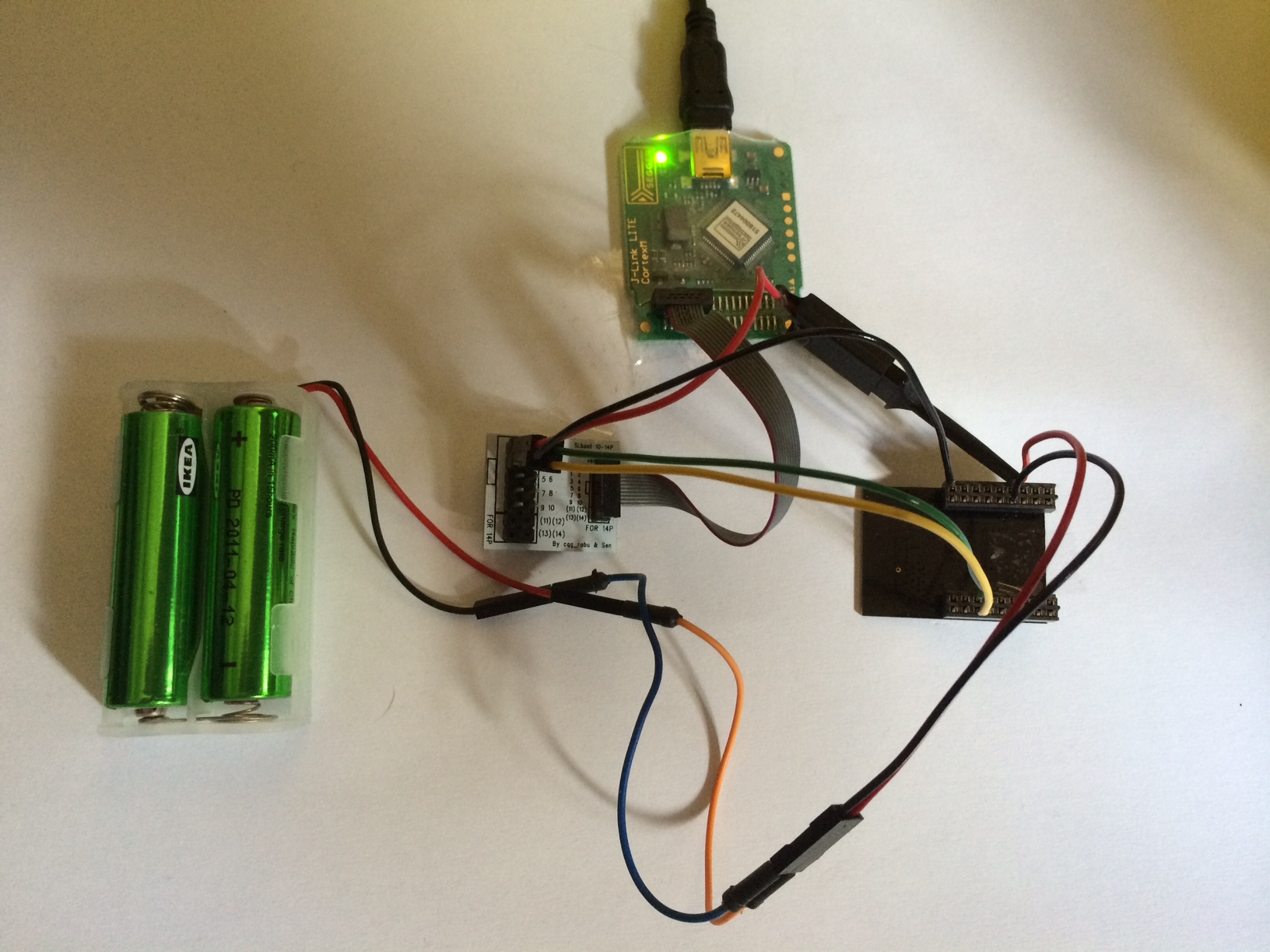
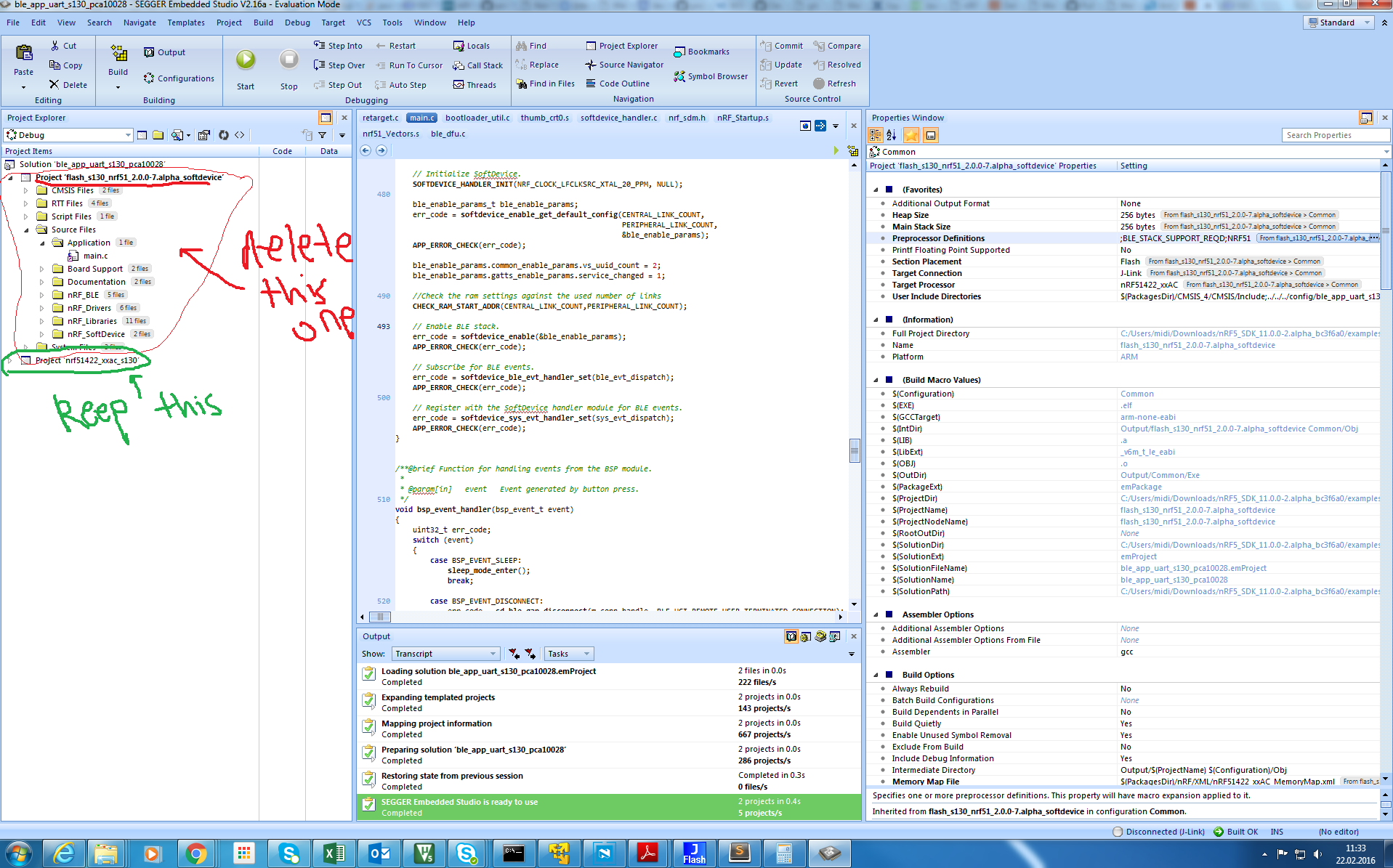
Both boards are powered from the PC USB port.Īll the measurements are done with a Rohde & Schwarz RTB2004 300 MHz 2.5GS/s oscilloscope using a RT-ZP03 300 Mhz 10:1 probe. I use this board for the experiments where I use Segger Embedded Studio to write the programs and use the J-Link connection to flash the program to the board.īoth micro:bit boards are connected to a Kitronik Edge Connector Breakout Board during experiments and the corresponding pin on the breakout board is connected to the oscilloscope probe. The other micro:bit is running a specific Segger firmware which enables J-Link OB (On Board). One is running the standard firmware, where a hex binary program can be copied to the MICROBIT folder, which is mounted when it is connected to the computer, and then it is automatically flashed to the board. I decided to use pin P8 on micro:bit which is connected directly to P0.18 on nRF51822. This processor does not have a special PWM feature, so a PWM signal has to be created using normal hardware features. SetupĪll experiments in this post is done with a BBC micro:bit (v1.5), which uses a Nordic Semiconductor nRF51822-QFAA Application Processor consisting of an ARM Cortex-M0 Processor at 16 Mhz. I examine what maximum GPIO toggling frequency is possible in this post.
#Segger embedded studio nrf51822 software#
It is definitely a theoretical maximum but since the processor is clocked at 16 Mhz, GPIO toggling by software can, I think, be done at maximum 16/3~5.3 Mhz, assuming writing 1 and writing 0 and then looping back to writing 1 can each be done in a single cycle. Basically I would like to write a 0 and then a 1 to a digital output, and repeat this forever, and I would like to see the frequency of the pulse train it generates and how different programming levels or abstractions affect this. I needed to generate a pulse train (square wave or PWM), and I had a micro:bit, then I wondered how quick you can toggle the digital outputs of the micro:bit to generate such a signal.
#Segger embedded studio nrf51822 series#
This is the first experiment of a potential series of posts related to lateny in computer systems.


 0 kommentar(er)
